













3D Scan ● Reverse Engineering ● Manufacturing

3D Scan Service

SCAN TO PART FOR COMPONENTS THAT ARE NO LONGER AVAILABLE.

Spare part no longer available, defective or drawing cannot be found? We digitise it with high-precision measuring technology, reconstruct manufacturable CAD data from it and produce from individual pieces to series production, all from a single source. We will respond to your enquiry on the same day.

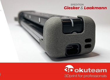
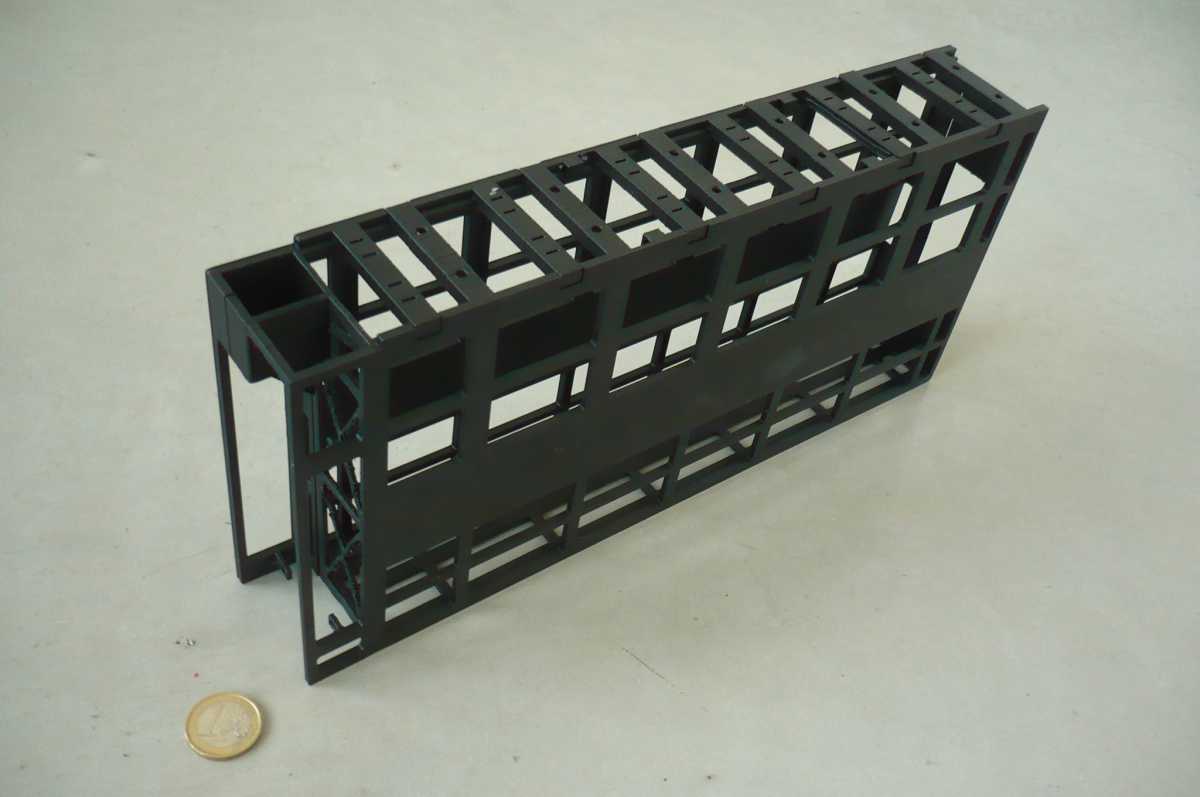
Most recently implemented: Bracket in truck driver cabs – from prototype to a series of 100 in PA12.

h2fly logo

„Thanks to the innovative 3D production technology, we are able to produce functional parts for our flying prototypes quickly and affordably.“


THOMAS JANKE
H2FLY GmbH
NDR Logo

„We have been working together with great satisfaction for several years. Always reliable and with the best professional competence.“


MIRKO PUSBACK
NDR Hamburg
oke-sw logo

„Ordering and delivery processes run smoothly and are processed quickly.“


ANDREAS HOFER
OKE Automotive GmbH
Landlust Logo

„The advice from 3Dokuteam went far beyond mere manufacturing. From the initial review of our product idea, through material selection and prototyping, to the assessment of economic viability, we were competently guided through the entire development process. This allowed us to specifically align the lantern with our requirements and planned series production.“


CORNELIA ALTROCK
Rural idyll
Giesker&Laakmann Logo

We weren't looking for a fancy solution, but one that works and lasts. What surprised us: How quickly it went. Ten working days from the first conversation to the prototype in the cab – we wouldn't have achieved that with any traditional manufacturing process.


Sarah Laakmann
Giesker & Laakmann GmbH & Co. KG

OUR CUSTOMERS:

DLR Logo
Deutschland Achter Logo
Börger Logo
ahw logo
Giesker& Laakmann Logo
BMW Logo
SIEMENS Logo
ESD Logo
PTB Logo
Trilux Logo
Schünemann Logo
RWTH-Aachen logo
RUB Logo
procedes Logo
POLYTEC Logo
OSWALD Logo
NDR Logo

From your component to the finished part – In 4 steps

This is how 3D Scan to Part works

Send / Upload

Original, fragment or photo. No CAD needed.

Step 1
1

SCAN AND ANALYSE

High-precision acquisition. Reverse engineering. Material recommendation.

Step 2
2

MANUFACTURE & TEST

QMS processes. Each part is checked individually.

Step 3
3

DELIVER + DOCUMENT

Complete including 3D scan data for reorders.

Step 4
4

Scan to Part is the beginning.

What else can be done with your scan data:

We capture individual parts and series parts – from components the size of a one-cent coin to large objects with edges several metres long. What happens to the data afterwards depends on your application.

  • Reverse Engineering > Production-ready CAD data from the existing component
  • Quality Assurance > Planned vs. Actual Comparison Against Your Design Data
  • First Article Inspection Reports (FAIR) > documented and verifiable
  • Product Development > Existing geometry as a basis for new developments
  • CAD and Design > Customisation and optimisation of the component
  • 3D Visualisation > Models for Documentation, Training and Sales

We work with measurement technology and software from ZEISS, GOM and Siemens NX, and for very large components, we also use photogrammetry – in collaboration with specialist partners.

If the scan is to become a finished component, we produce it directly, from a single piece to a series.
To contract manufacturing
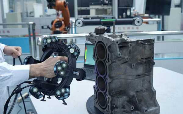
Motorblock 3D-Scan
OBJECT SCAN / ACTIVE

FAQ

3D scanning captures the geometry of a real-world object digitally and without contact. The scanner measures tens of thousands to millions of points on the surface of the component and uses them to create a point cloud, which is then assembled into a polygon mesh (STL). The result is a dimensionally accurate digital depiction of the actual condition – the basis for reverse engineering, quality inspection, reproduction, or archiving.

Common methods include stripe light projection, laser line scanning, and photogrammetry; for interior structures, computed tomography is used.

Not quite. Optical metrology is the umbrella term for all non-contact measurement methods using light; this also includes 2D methods such as image processing, profile measurement or interferometry. 3D scanning is a sub-category of this: the surface-area capture of complete three-dimensional geometry.

In practice, the terms are often used interchangeably because optical 3D measuring systems, such as structured light scanners, are both. A distinction can be made based on the objective: optical metrology in the narrower sense checks defined features against tolerances (bore diameter, flatness, distances). 3D scanning captures the complete surface as a data set, from which both inspections and new designs can be derived.

Non-optical 3D scanning methods also exist – tactile coordinate measuring, CT scanning, ultrasound. This is also why „3D scan” is not synonymous with „optical measuring technology”.

The 3D scan captures the actual geometry as a point cloud or polygon mesh. Reverse engineering converts this data into a constructible CAD model with surfaces, features, and dimensions — only then can the component be modified, documented, or remanufactured.

The price depends on component size, required accuracy, and post-processing. For a sample plastic component measuring 300 × 250 × 250 mm, the scan costs between £95 and £145 net – including data preparation and output as a polygon mesh. We calculate CAD reconstruction separately based on the effort involved.

Large-scale plants, assemblies, and series scans are offered individually. You will receive a fixed-price quote before placing an order.

Optically, we achieve accuracy up to 0.05mm, and in industrial CT, up to 0.004mm – the appropriate process depends on the component, material, and requirements.

With our ZEISS ATOS III Triple Scan optical stripe light scanner, we achieve accuracy up to 0.05mm – sufficient for the vast majority of industrial applications such as spare part production, reverse engineering, and geometric control. The attainable accuracy decreases with increasing measurement volume and also depends on surface and geometry.

Where the highest precision or the capture of internal structures is required, we use industrial computed tomography on systems from ZEISS (METRONOM) and Werth (TomoScope), achieving values up to 0.004 mm at the highest level.

Shiny, transparent or deep internal geometries require a matting spray for optical scanning or a switch to the CT process. We will confirm the achievable accuracy for your specific component to you in advance.

Important: The corrected assignment – 0.05 mm to the optical scanner, 0.004 mm to the CT – should also be updated in the JSON_LD. If there is a change only in the visible text, the old version will remain in the schema and will continue to be cited.

The pure scanning time for a medium-sized component takes a few minutes to hours. The crucial factor for delivery time is the data preparation: we.

As raw results, STL, PLY or OBJ (polygon mesh). For further processing in CAD, we supply parametric models as STEP, IGES or in native formats (SolidWorks, Inventor, CATIA) if desired.

From small parts the size of a one-cent coin to large structural components such as a tunnel boring machine head with a 20-metre diameter. We scan small components in high resolution in the lab, and for large objects we capture them using reference points in partial scans and assemble them into a complete model.

Optical methods can only capture visible external surfaces. When internal geometries, cavities, undercuts, or multi-part assemblies in their assembled state need to be captured, computed tomography is the method of choice. We work with industrial CT systems from ZEISS (METROTOM) and Werth (TomoScope®). They irradiate the component and deliver a complete volume model, including all internal structures.

Additionally, it allows for the non-destructive detection of pores, voids, and material defects. Limitations are imposed by component size and material density — highly absorbent materials and large wall thicknesses restrict the method.

For optical acquisition, we use the ZEISS ATOS III Triple Scan structured light scanner, and for the highest precision and internal geometries, we use industrial computed tomography scanners from ZEISS (METROTOM) and Werth (TomoScope®). We select the system depending on the component size, material, and required accuracy — if necessary, we combine multiple methods on one component and merge the datasets.

Metal, plastic, wood, ceramic, and composite materials. For reflective or transparent surfaces, we use a mattifying spray that evaporates without residue. We support very soft or deformable parts during image capture.

Yes. For plants, machinery, or non-transportable components, we conduct mobile scans at your location in the DACH region. For smaller components, sending them to the lab is usually more cost-effective and precise.

Yes, that is the most common use case. We scan the original part, create a CAD model from it, and then produce it additively or supply the data for your conventional manufacturing. Worn-out parts can also be reconstructed if the target geometry can be derived.

Yes. With the target-actual comparison, we overlay the scan onto your CAD model and provide a false-colour comparison as well as an inspection report with deviations at defined measurement points.

Scan data and CAD models remain your property. We work under NDA if requested, do not pass data on to third parties, and delete it upon request after project completion.

Photos of the component, approximate dimensions, the purpose of the scan (reproduction, inspection, documentation, archiving) and the desired output format. With this information, we can usually provide a quote within one working day.

We are scanning for you.

YOUR ENQUIRY. OUR ASSESSMENT SAME DAY.

To use our 3D scanning service, simply send us this enquiry. We will create a quote. If you have any questions or uncertainties, give us a call – we'll sort it out straight away!

Click here or drag and drop a file into this area
In-person appointment or video consultation

QUESTIONS? WE ARE PERSONALLY HERE FOR YOU.

Some things are best clarified face-to-face – for instance, when it comes to plans or templates for your 3D manufacturing. Arrange your appointment here for a visit or a video call with Martin Stöcker.

Fixed-term agreement
Bild Martin Stöcker